Transistor Darlington Pair Tutorial
- the Darlington pair, or super-alpha pair consists of two devices (transistors) with the emitter of the first connected to the base of the second to give very high gain levels..
Fundamental transistor circuits include:
• Transistor Darlington• Darlington pair circuits
• Sziklai / compound pair
• Quasi-complementary output
• Current mirror
• Transistor long tailed pair
• Constant current source
The Darlington Pair is a useful circuit configuration for many applications within electronic circuits. This circuit configuration provides a number of advantages that other forms of transistor circuit are not able to offer and as a result it is used in many areas of electronics design. The Darlington Pair also occasionally referred to as a super-alpha pair is renowned as a method for obtaining a very high level of current gain, using just two transistors. It is able to provide levels of gain that are not possible using single transistors on their own, but it may not be used in all circumstances because it does have a number of limitations.
The circuit may be used in the form of discrete components, but there are also very many integrated circuit versions often termed a Darlington transistor that may also be used. These Darlington transistor components may be obtained in a variety of forms including those for high power applications where current levels of many amps may be required.
The Darlington Pair has been in use for very many years. It was invented in 1953 by Sidney Darlington who was working at Bell Laboratories. He developed the idea of having two or three transistors in a single semiconductor chip, where the emitter of one transistor was connected directly to the base of the next, and all the transistors shared the same collector connection. In many ways the Darlington bore many of the hallmarks of the first integrated circuit patent, but it was too specific to the specific Darlington circuit itself to be considered as an integrated circuit.
Basics
When using an emitter follower in a circuit, the level of current gain, and the input impedance of the circuit is limited by the current gain that can be achieved using a single transistor. The gain of the Darlington transistor pair is that gain of the two individual transistors multiplied together.

In view of the fact that the terms βQi and βQ2 on their own can be neglected, we obtain the more familiar equation.

The basic circuit is formed by taking the emitter of the input transistor and connecting it such that its emitter drives the base of the second and then connecting both collectors together. This circuit can be used as any single transistor would be in a variety of circuits, but particularly as an emitter follower.
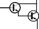
In many respects a Darlington pair can be treated like a single transistor with a very high gain, and in these instances it is often shown on a circuit diagram as a single component.
While the Darlington can be viewed almost as a circuit block or component in its own right, it does have several differences between it and the basic transistor. For example it has a higher voltage difference between the overall base and emitter, i.e. from the base of the input transistor to the emitter of the output transistor.
This means that for a typical silicon device, the overall base emitter voltage required to turn the Darlington pair on is two times 0.7 volts, i.e. 1.4 volts.
A further point to note is that the saturation voltage of the Darlington configuration is about 0.7 volts. This is higher than that of a single transistor, where, for example a switching transistor may exhibit a saturation voltage of around 0.2 volts. The increased level of saturation voltage of the Darlington pair needs to be considered in some applications where high currents are passed because it may result in significant levels of power being dissipated in the device.
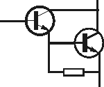
It is also necessary to be aware that the Darlington Pair is not as fast as a single transistor. This is because the first transistor cannot actively shut off the base current of the second transistor. In turn this makes the overall device or circuit configuration slow to reduce the current flow or switch off. To address this problem, the second transistor often has a resistor connected between the base and emitter. This resistor also helps prevent any leakage current from the input transistor from turning the output transistor on. This leakage current can be of the order of nano-amps for a small signal transistor or up to a few hundred micro-amps for a power transistor. The value of the base emitter resistor is chosen so that it does not sink a large proportion of the current intended to pass through the base of the output transistor, while not allowing the leakage current to develop a voltage equal to the turn on voltage of the output transistor to be developed. Typical values for the resistor may be a few hundred ohms for power applications for the circuit or a few thousand ohms for a small signal version.
When using a Darlington pair configuration in a new electronics design, it is necessary to account for the fact that it has a greater phase shift at high frequencies than a single transistor. This can result in the overall circuit having a greater likelihood of becoming unstable if negative feedback is used in the circuit.
Often when making a Darlington pair, the output transistor is required to be able to handle high levels of current. High power transistors typically have lower levels of current gain than the small signal varieties. This means that often the input device is a small signal high gain variety, whereas the output transistor is a high power device with an inherently lower current gain.
Advantages and disadvantages summary
While the Darlington pair offers many advantages they also have limitations. Accordingly when considering its use, it is necessary to weigh up both sides of the equation.
| ADVANTAGES: | DISADVANTAGES: |
|---|---|
|
|
The Darlington pair transistor circuit configuration can be very useful in electronics circuit design. Although it has speed limitations, the circuit is nevertheless very useful in many areas where high levels of current gain are required, particularly for emitter follower style applications.
Although the Darlington pair is most usually referred to by this name, the older name - the super-alpha pair may still be used on some occasions. Today, the term Darlington is the most widely used.
By Ian Poole
thanks for sharing such a beautiful information. please keep more sharing about Darlington transistor
回复删除